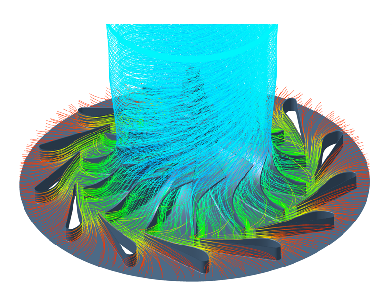
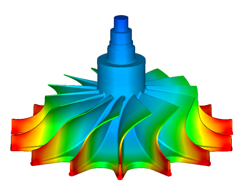
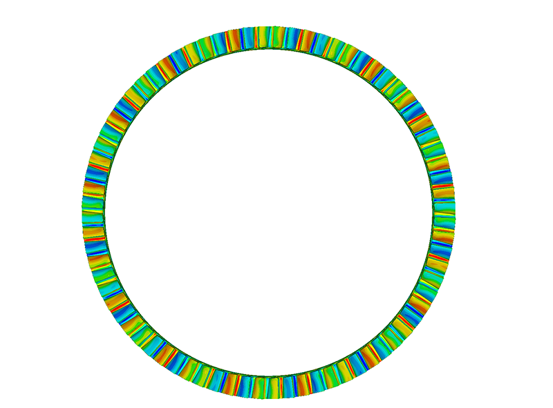
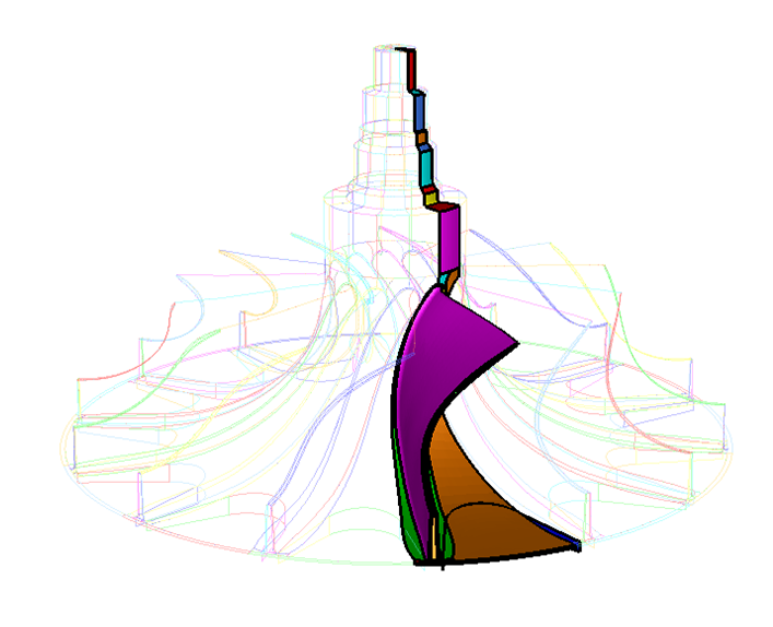
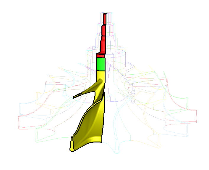
The development of turbomachinery with increasingly higher levels of efficiency makes the detailed knowledge of the mechanical, thermal and fluid dynamic processes indispensable. They serve for optimizations of the flow geometry, thermal stresses, lifetime, etc. The realistic simulation of the turbomachinery system often requires the knowledge of boundary conditions, which usually are the results of other simulation disciplines or even are strongly interrelated with each other.
In order to consider those interactions (“multiphysics”), a mapping (using MpCCI FSIMapper) or a coupled simulation (MpCCI CouplingEnvironment) is required.
Turbomachinery Applications
Tabbed contents
Reference Applications
Blade Deformation and its Influence to the Fluid Flow
In operation, the fluid pressure field leads to deformations of the blades and thus to a change of the flow channel, which in turn influences the pressure field and the performance of the machine.
A coupled simulation (via MpCCI CouplingEnvironment) of the turbomachinery CFD analysis and the structural analysis - where the pressure and the deformation are exchanged - computes this fluid-structure-interaction.
If the influence of the blade deformation to the fluid flow is negligible, also a mapping of the pressure field to the structure is sufficient (MpCCI FSIMapper).
- Recent Progress in Flow Control for Practical Flows
Chapter 15 "Analysis and Optimization of Flow Around FlexibleWings and Blades Using the Standard Co-simulation Interface MpCCI"
Thermal Loading Resulting from the Fluid Flow
In order to compute a realistic temperature distribution in turbomachinery for the solution of the heat transfer equation, well-chosen thermal boundary conditions are necessary. This includes, among other things, the heat input from the flow. The heat flux is influenced by the difference between fluid and wall temperature. The wall temperature is in turn dependent on the active heat flux. Only if both quantities are at equilibrium, the actual component temperatures are reached.
In some applications it is sufficient to map the film temperature and the heat transfer coefficient once to the thermal structural simulation. With this boundary condition, a thermal stress analysis can be performed.
Flow-Induced Vibrations
Flow-induced vibrations can lead to a high noise emission and to blade fatigue which can endanger the integrity of the whole system. The excitation is caused by pressure fluctuations in the flow field generated by interactions between rotating and stationary blade rows. Structural vibration analyses operate in frequency domain which offers fast simulation methods. This means, that the exciting transient pressure fields have to be transferred to the frequency domain in order to meet the prerequises as a vibrational boundary condition.
MpCCI Methods
Features for Turbomachinery Applications
- Mapping: file-based unidirectional data transfer MpCCI FSIMapper
- Coupling: data exchange at run-time MpCCI CouplingEnvironment
- Support of unequal mesh densities or element types
- Support of unequal geometry details
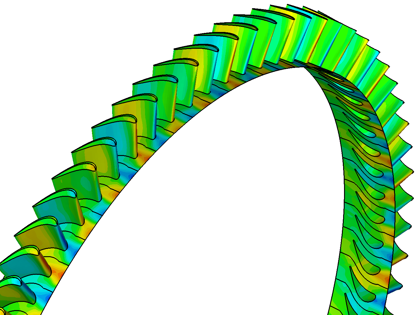
- data transfer/exchange between periodic models which exhibit different section shapes and positions (also full models)

- map the average of all periodic sections for steady state frozen rotor/MRF simulation results which do not necessarily exhibit rotational symmetry
- perform a Fourier transformation on transient data to create and map the loading for vibration analyses
- map harmonic CFD results having regard to the data’s inter-blade phase angle


Realization of new Methods and Solutions within R&D Projects
- Coupling of harmonic simulations in frequency domain. This new feature enables a fast coupling of structural vibration and harmonic CFD analyses in order to calculate the steady state of the the fluid structure interaction.
Software and Services
Service Offer
- Integration of commercial or inhouse codes into the MpCCI tools
- Integration of MpCCI tools into customer’s CAE workflow
- Adjusting MpCCI to customer’s specific requirements
MpCCI CouplingEnvironment
The MpCCI CouplingEnvironment offers flexible solutions for multiphysical simulations. The combinable simulation codes for this application area are shown in the following table:
Discipline |
Codes |
|---|---|
Fluid |
|
Heat Transfer |
|
Structure |
|
The supported quantities in this context are:
Quantities |
|
|---|---|
Mechanical |
|
Thermal |
|
MpCCI FSIMapper
The MpCCI FSIMapper maps simulation results from a source to a target mesh. The following two tables list the supported source and target file formats for this application area.
Source Formats |
Quantities |
|
|---|---|---|
CFD |
|
pressure temperature heat flux film temperature, heat coeff. |
Target Formats |
Target Analyses |
|
|---|---|---|
FEM |
|
deformation stress heat transfer NVH fatigue |
List of additionally supported source and target file formats
